1 Purpose
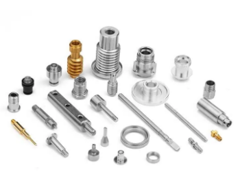
To standardize the processing and inspection criteria for CNC machined products and to provide a reliable basis for adjudicators.
2. Scope
Applicable to the reliability verification and appearance inspection of CNC machined workpieces of our company and outsourcing factories
3 Inspection items and definitions
3.1 Tool pattern: the pattern resulting from tool wear or oscillation, usually tactile and wave-like.
3.2 bruising: collision or drop stroke collapse shape due to improper handling.
3.3 porosity, trachoma: irregular hole-like defects or honeycomb-like black spots formed due to insufficient casting density.
3.4 abrasion: due to improper operation of the product friction formed strip defects, or due to the tool with residual cutting waste formed spiral line defects.
3.5 segmental differences (steps): due to poorly bevelled tool paths, forming step-like defects.
3.6 burrs: due to the radial force of the tool resulting in local cutting waste not detached from the workpiece to form jagged or strip defects.
3.7 missing material: due to excessive cutting force after tool wear resulting in chipping or missing flesh at weak points of the product.
3.8 rotten teeth: due to small or large tapping base diameter, skewed bottom hole, taps wear resulting in local disorder of threads, no threads, tooth shape does not match
3.9 Crushing: impurities are pressed into the product as a result of cutting residues in the machining tool or by external forces, resulting in a sunken defect.
3.10 Cracking: tearing defects at weak points due to insufficient casting density or excessive cutting forces caused by tool wear.
3.11 poor cutting: due to the product in the jig fixed position offset or tool relative coordinates change caused by cutting too much or too little; including overcut or undercut, where undercut is also called more material.
3.12 hole deviation: due to improper positioning or skewed reinforcement column, or even uneven shrinkage of the die-cast product resulting in deviation of the hole position from the centre of the reinforcement column where the hole is located.
3.13 bad chamfering: due to assembly or safety factors on the sharp edge of the product process chamfering, if there are no special requirements in accordance with C0.2 ± 0.1 control, thread chamfering shall ensure that the tapping phi is not higher than the top surface of the screw column (i.e., the height of the phi should be lower than the height of the chamfer), bad chamfering is divided into two conditions: a, chamfering is too large, due to the tool or program control there is too deep eating knife, resulting in chamfering is large or chamfering is small. After chamfering, there are sharp edges or flanged edges; b. Uneven chamfering (chamfering small and large edges), due to product deformation or fixture clamping there is loose, resulting in chamfering width there are irregular shapes, fixture clamping loose often accompanied by vibration knife pattern.
3.14 Flat (shallow) threads: The threads are tapered when viewed visually because the thread bottom hole is too large, resulting in slippage or insufficient torque.
3.15 Structural discrepancies: the product does not match the 3D inventory, often due to over- or under-materialization or a discrepancy in the roundness of the hole (shaft or column).
3.16 Deformation: Due to the influence of the workpiece material, the thickness and toughness of the workpiece change after machining, which changes the original shape of the workpiece, resulting in an uneven or distorted product shape.
4 Judgement method
4.1 A-level surface: the surface of the product directly exposed after assembly, usually speaking of the appearance of the surface
4.2 B-grade surface: the surface of the product that is not directly exposed after assembly but can be directly observed after rotation at a certain angle
4.3 Class C surfaces: surfaces that are not directly exposed after assembly and that can be observed only after the removal of certain parts.
4.4 Linear class defect judgment method
Length * width * depth * number
L *W *H *N
4.5 Hole-like defects
Area * Depth * Number
A *H *N
5 CNC machined workpiece inspection criteria
CNC workpiece acceptance criteria and defect levels
| Inspection items | Acceptance criteria | Inspection tools and methods | Defect description | Defect level | ||
|---|---|---|---|---|---|---|
| Lethal | Severe | Slight | ||||
| Appearance | No scratches, colour differences or bruises on the surface | Caliper drawing hand feel plug gauge | Fine scratches, colour differences, bruises | √ | ||
| No dents, sand holes, knife scratches, impurities on the main view surface | Dents, sand holes, knife scratches, impurities on the main view | √ | ||||
| Two other (left, right or top and bottom) sides with 0.1mm diameter dents, sand holes, impurities | √ | |||||
| No fracture, perforation or missing material on all parts of the product | Fractures, perforations, missing material | √ | ||||
| All edges must be of uniform thickness | Uniform thickness on all edges | √ | ||||
| If there is a brushed pattern, it must be clear and consistent in direction | Unclear and inconsistent drawing pattern | √ | ||||
| All holes and edges are free of prickly burrs | Prickly burrs at each hole and edge | √ | ||||
| Structural performance reliability | Dimensions and tolerances are in accordance with technical requirements and do not affect assembly | Not in accordance with technical requirements | √ | |||
| Clear tooth path, good fit and seal (gap) less than 0.1mm | Difficult assembly and sealing (gap) greater than 0.1mm | √ | ||||
| No deviation, penetration or leakage of holes | Hole position is off, punched through or missed | √ | ||||
| The flatness of the upper and lower surfaces is less than 0.3mm | Flatness of top and bottom surfaces greater than 0.3mm | √ | ||||
| No air holes are allowed on secondary surfaces after machining | Air holes on secondary surfaces after machining | √ |
CNC Machining Standard
| Serial number | Inspection content | Inspection standards |
|---|---|---|
| 1 | Finishes | 1、Split surface and material position surface processing fan height h≤0.001mm; 2、avoidance of empty position surface processing fan height H=0.003mm-0.005mm; 3、flat processing without obvious scratch round knife pattern; 4、finishing surface without obvious bullet knife pattern; 5、no water ripple after surface bare knife; 6、inlet point into the knife mark grade difference ≤0.02mm; 7、R angle bit processing smooth, no No stepped cutter pattern. |
| 2 | Joint marks | The grade difference of the jointing position is ≤0.02mm when the workpiece is processed |
| 3 | Corner clearance | 1、Finishing part without popping tool marks, smooth and excessive; 2、Finishing part with ≤0.02mm grade difference in the joint position; 3、Leaving EDM part according to the tool length-diameter ratio of 1:5 to clear the angle. |
| 4 | Machining allowances | 1、Light in place ≤ 0.02mm; 2、Insert through surface in the convex side stay ≤ 0.05mm; 3、To be EMD bit ≤ 0.15mm, horizontal bottom surface ≤ 0.05mm; 4、Deep cavity open rough bit ≤ 0.35mm |
| 5 | Data inspection | 1、Processing error ≤0.03mm (single side); 2、Location tolerance ≤0.03mm |
| 6 | Degree of finish | 1、Complete all items required by CNC program sheet; 2、Additional items required by drawings |
CNC machining workpiece appearance inspection standard
| Inspection items | Noodle category | Qualifying range | Remarks |
|---|---|---|---|
| Knife pattern | A | NG | The chamfer can have a uniform vibration pattern that is not perpendicular to the direction of processing by hand |
| B | No feel is OK, no significant difference from the substrate, no water ripples | ||
| C | Slight handfeel allowed, does not affect structure OK | ||
| bruising and crushing | A | A≤0.05;H≤0.05;N≤1 | Single face rule; no more than 2 defects in total on a single product |
| B | A≤0.1;H≤0.1;N≤1 | Single face rule; no more than 2 defects accumulated in a single product | |
| C | A≤0.5;H≤0.2;N≤3 | Single face rule; no more than 5 defects accumulated in a single product | |
| Scuffs | A | L≤1;W≤0.05;H≤0.05;N≤1 | Single face rule; no more than 2 defects accumulated in a single product |
| B | L≤2;W≤0.1;H≤0.1;N≤1 | Single face rule; no more than 2 defects accumulated in a single product | |
| C | L≤3;W≤0.3;H≤0.2;N≤2 | Single face rule; no more than 5 defects accumulated in a single product | |
| Pores and trachoma | A | A≤0.05;H≤0.05;N≤2 | Single face rule; no more than 3 defects in a single product |
| B | A≤0.1;H≤0.1;N≤3 | Single face rule; no more than 3 defects in a single product | |
| C | A≤0.5;H≤0.2;N≤4 | Single face rule; no more than 5 defects accumulated in a single product | |
| Segmentation | A | NG | |
| B | NG | ||
| C | H ≤ 0.02 and no influence on the actual assembly | where H is the height of the segment difference | |
| Burrs | A | NG | |
| B | NG | ||
| C | NG | ||
| Missing material | A | NG | |
| B | NG | ||
| C | NG |


