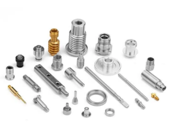
In the following post, we will review the general design rules for machining. These are fairly basic rules, and you will have a better chance of success once you know them.
Tolerances to be considered
In general, the tolerances of a part are determined by the application, but there are some general guidelines:
Sawing or drilling holes in thin sheet metal should be made with a tolerance of ±0.002 in. (0.05 mm). A hole drilled in thick metal should have a tolerance of ±0.005 in. (0.12 mm).
Threaded holes in thin sheet metal should be within ±0.003 in. (0.08 mm) of the specified size; threaded holes in thick metal should have a tolerance of ±0.006 in. (0.15 mm).
If two parts fit together, they must be cut according to their tolerances to match exactly when assembled correctly.

Corner features and Wall thicknesses
When machining corners, the depth of cut should be reduced to avoid chip packing. For example, a 0.5 mm diameter corner feature should have a 0.2 mm depth of cut. This will allow chip packing and leave enough material to support the corner feature during machining.
The wall thickness of a feature should be at least three times the diameter of the smallest tool used to machine it. For example, if the smallest tool used to machine a feature is 0.25 mm in diameter, then at least 0.75 mm wall thickness should be left in place after milling that part of the workpiece away. The remaining portion can be machined away later with larger tools if necessary.

Select material properly
Selecting the right material for your job is critical to achieving the desired part quality and minimizing machining costs. Here are some general guidelines:
Use cost-effective materials. The lower the cost of the material, the less expensive it will be to machine. Materials requiring more machining generally cost more per pound or piece.
Look for low-cost alternatives. Consider using aluminum alloys (for example, 2024), magnesium alloys (such as AZ91D), or plastics when possible. If a plastic or other material requires too much machining, consider using a solid model rather than a surface model — or find another way to design your part so it can be machined with less effort.
Consider secondary operations. For example, if you need to machine slots into a casting or weldments onto an aluminum plate, consider adding these operations after molding or casting instead of during primary machining operations.
Minimize finish requirements by selecting appropriate tooling options for your application.

Draft angles
The draft angle is the angle between a part’s surface and the cutting tool’s direction. It is used to reduce chatter and increase chip thinning. The greater the draft, the more effective it is at reducing chatter.
Draft angles can be used in many different ways:
Increasing the draft angle makes the material easier to cut and increases tool wear. Therefore, it should not be used on parts that require high accuracy or tool life.
Adding a small back rake or relief angle will help prevent chatter by providing a slight clearance for chips to escape between the tool’s cutting edge and the workpiece as they form. This also helps prevent blow holes in turning operations due to chips trapped between the tool and workpiece.

Machining allowances
Machining allowances are the tolerances that allow for the expansion and contraction of the part during machining. The allowance amount varies with material, tooling, and machine capabilities, but it should be kept as low as possible to avoid excessive tool wear and tear.
The following guidelines will help you determine the proper machining allowance:
Material: A 1/64-inch (0.4 mm) machining allowance is adequate for most materials. Other considerations include work hardening and heat treatment, which can cause parts to expand more than normal.
Machine capability: Use the maximum cutting depth specified by your manufacturer or service provider to determine your machining allowance. If this information is unavailable, use a 1/16-inch (1.6 mm) allowance per side of the part when cutting through hardened steel or other high-strength materials.

Arrangement of components on a casting tree
The arrangement of components on a casting tree is important for several reasons.
1. It must be possible to set the positions of all the components accurately about each other and the casting base so that they can be machined without interference. This may require special fixtures or other devices to position them correctly.
2. If there are any holes in the parts, they must fit together properly when assembled on the casting tree. This means that they must be placed so that all holes are within tolerance limits and do not interfere with each other when assembled on the casting tree.
3. The distance between adjacent components should be small enough to allow easy access by tooling but large enough so that one part does not interfere with another during machining operations such as milling or drilling where cutting tools enter from opposite sides (i.e.,,, end mills or drill bits).

Draft requirements on internal corners and surfaces
The draft angle for internal corners should be at least 2 degrees for material with a hardness value of less than 60 HRC and 3 degrees for material with a hardness value greater than 60 HRC.
The draft angle for internal surfaces should be at least 0.5 degrees.
If the surface finish is required to be better than the surface roughness of 0.15 μm ( Ra = 0.15 μm), then the total draft angle must be more than 0.2 degrees.

Conclusion
If you are designing a part that is going to be machined, then you must follow the design rules in order to ensure your part can be easily manufactured. These rules ensure that the material is removed from the tooling repeatedly during manufacturing without damaging the critical dimensions of your part. If these rules were not followed and critical dimensions were compromised, the entire product would be useless and likely need to be remanufactured. By using these design rules in conjunction with 3D modeling software and 3D printing software, designers can be sure that their product designs are manufacturable by machining.


