(l) Before writing or programming, the processing program of the workpiece should be compiled first. Suppose the processing program of the workpiece is long and complicated. In that case, it is best not to program on the machine tool but to use the programming machine or computer programming, which can avoid occupying the machine’s time. And should also be written on the program list for short programs.
(2) Generally, the machine tool is turned on first, and then the system is turned on. In some designs, the two are interlocked, and information cannot be displayed on the CRT if the machine tool is not powered.
(3) Return to reference point For the machine tool with an incremental control system (using incremental position detection element), this step must be performed first to establish the movement reference of each coordinate of the machine tool.
(4) Adjusting the program According to the storage medium of the program (paper tape or magnetic tape, disk), it can be input with a paper tape reader, a cassette tape machine, a programming machine, or serial communication. If the program is simple, the keyboard can be directly used on the CNC control panel. If the program is very simple and only one piece is processed, there is no need to save the program. The MDI method can be used to input and process segment by segment. In addition, the workpiece origin, tool parameters, offsets, and various compensations used in the program must also be input before processing.
(5) Editing of the program If the input program needs to be modified, it must be edited. Then, put the mode selection switch to the edit position, and use the edit key to add, delete, and change. See the corresponding manual for the editing method.
(6) The machine tool is locked, and the program is run. This step is to check the program. If there is an error, it needs to be edited again.
(7) Manual incremental movement, continuous movement, or manual wheel movement of the machine tool are used for loading the workpiece and aligning the tool. Set the starting point to the beginning of the program, and set the tool’s reference.
(8) Starting coordinate feed for continuous processing generally uses the program in the memory for processing. This method has a lower failure rate than the program processing on paper tape. The feed override switch can adjust the feed rate during processing. During processing, you can press the feed hold button to pause the feed movement, observe the processing situation or perform the manual measurement. Press the cycle start button again to resume processing. To ensure the program is correct, it should be re-checked before machining. During milling, for flat, curved workpieces, a pencil can be used instead of a tool to outline the workpiece on the paper, which is more intuitive. If the system has the tool path simulation function, it can be used to check the correctness of the program.
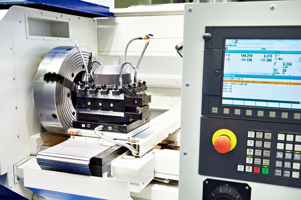
(9) Operation display Display the position of the workbench or the tool, the program, and the state of the machine tool by using each CRT screen so that the operator can monitor the processing situation.
(10) After the program output processing, if it is necessary to save the program, it can be left in the CNC memory. If the program is too long, the program in the memory can be output to an external device (such as a punching machine), and the program in the punched paper tape (or tapes, disks, etc.)
(11) Shutdown should generally shut down the machine tool and the system.

Matters needing attention in the operation of CNC milling machine
(l) Before starting each machine, check whether the lubricating oil in the lubricating oil pump behind the milling machine is sufficient, whether the air compressor is turned on, and whether the mechanical oil used for the cutting fluid is sufficient, etc.
(2) When starting up, first turn on the main power supply, then press the ON button in the CNC power supply, turn the emergency stop button clockwise, and wait for the milling machine to detect all functions (a row of red indicators lights on the lower operation panel turns off) , press the machine button to reset the milling machine and put it in the standby state.
(3) During manual operation, you must always pay attention that the Z axis must be in the position of raising the knife before moving in the X and Y directions. During the moving process, you can not only watch the change of the coordinate position on the CRT screen but also observe the movement of the tool. After the tool moves in place, you can watch the CRT screen for fine-tuning.
(4) In the programming process, for beginners, the G00 command should be used as little as possible, especially in the three-axis linkage of X, Y, and Z; more attention should be paid. When emptying the knife, the movement of the Z axis should be carried out separately from the movement of the X and Y axes, that is, more lifting of the knife and less oblique insertion. Sometimes due to the oblique insertion, the tool will hit the workpiece, which will be damaged.
(5) When using a computer for serial communication, turn on the milling machine first, then turn on the computer; turn off the computer first, then turn off the machine.

Avoid the milling machine from impacting the computer due to the instantaneous current change during the switching process.
(6) When using the DNC (program transfer between the computer and the milling machine) function, pay attention to the memory capacity of the milling machine. Generally, the total number of bytes of the program transferred from the computer to the milling machine should be less than 23kB. If the program is relatively long, it must be processed by the computer while transmitting, but the block number must not exceed N9999. If there are more than 10,000 blocks, you can cancel the block number with the program editing function in MASTERCAM.
(7) When an alarm occurs on the milling machine, it is necessary to determine the reason according to the alarming number and release the alarm in time. Do not shut down the machine. Otherwise, it will still be in an alarm state after it is turned on.
Using the edge finder to set the knife, the detailed steps are as follows:
(1) X, Y direction tool setting
① Install the workpiece on the machine table through the fixture. When clamping, the workpiece’s four sides should leave the edge finder’s measuring position.
② Quickly move the worktable and the spindle to make the edge finder probe close to the left side of the workpiece;
③Use the fine-tuning operation instead, let the probe slowly touch the left side of the workpiece until the edge finder lights up, and record the X coordinate value in the machine tool coordinate system at this time, such as -310.300;
④ Lift the edge finder to the upper surface of the workpiece, quickly move the table and the spindle, and make the probe close to the right side of the workpiece;
⑤Use the fine-tuning operation instead, let the probe slowly touch the left side of the workpiece until the edge finder lights up, and write down the X coordinate value in the mechanical coordinate system at this time, such as -200.300;
⑥If the diameter of the probe is 10mm, the length of the workpiece is -200.300-(-310.300)-10=100; according to this, the X coordinate value of the origin W of the workpiece coordinate system in the machine tool coordinate system is -310.300+100/2+ 5 = -255.300;
⑦Similarly, the Y coordinate value of the workpiece coordinate system origin W in the coordinate machine system can be measured.
( 2 ) Z-direction tool setting
①Remove the edge finder and install the tool used for processing on the spindle;
②Place the Z-axis setter (or a fixed-height tool setting block, the same below) on the upper plane of the workpiece;
③ Quickly move the spindle to make the end face of the tool close to the upper surface of the Z-axis setter;
Use the fine-tuning operation instead, and let the end face of the tool slowly touch the upper surface of the Z-axis setter until its pointer indicates the zero position;
⑤ Write down the Z value in the machine coordinate system at this time, such as -250.800;
⑥If the height of the Z-axis setting device is 50mm, the Z coordinate value of the workpiece coordinate system origin W in the coordinate machine system is -250.800-50-(30-20)=-310.800.
(3) Input the measured X, Y, and Z values into the machine tool-workpiece coordinate system storage address (generally use G54-G59 codes to store tool setting parameters).

Matters needing attention
Pay attention to the following issues during the tool setting operation:
(1) Use the correct tool setting tool according to the processing requirements to control the tool setting error;
(2) During the tool setting process, the tool setting accuracy can be improved by changing the fine-tuning feed;
(3) Caution should be exercised when setting the knife, especially the direction of movement to avoid the danger of collision;
(4) The tool setting data must be stored in the storage address corresponding to the program to prevent serious consequences due to calling errors.

Input and modification of tool compensation value
According to the actual size and position of the tool, input the tool radius compensation value and tool length compensation value to the storage location corresponding to the program.
It should be noted that the correctness of the compensated data, the correctness of the symbols, and the correctness of the address where the data is located will threaten the processing, resulting in a crash hazard or scrapped processing.


